31 Oct 2013

Revamped Wiki Help Site

The Autodesk Wiki Help site has had a major overhaul and is now faster, more streamlined, and brings a new visual style which closer matches the theme of the main Autodesk site.  The information contained within is now more up-to-date for your 2014 products and services.


Do bear in mind though; while it can provide information on tools and techniques, it still can't solve your problems - unlike us here at Micro Concepts.

If you have a support contract with us, do remember to give us a call on 01223 716 214 if you encounter any issues, or if you just need clarification on any of the advice listed on the wiki site.

29 Oct 2013

Inserting Inventor DWG views into AutoCAD

When you open an Inventor DWG in AutoCAD, it opens in Layout view.  If you would like to work on it in Model space, you can do so with the DDINSERT command.

1) Open the Inventor DWG in AutoCAD.  It will open in Layout view.


2) From Model space, type DDINSERT.  The Inventor drawing should automatically be selected.


3) Choose which view from the drawing you would like to insert from the drop-down Name menu.

4) Adjust your insertion and scale settings


28 Oct 2013

Windows 8.1 incompatability


Windows 8.1 is not fully supported by Autodesk software at this time.

From our tests so far, and from the official Autodesk blog, Vault is not compatible with the new operating system update.  We were successfully able to load our clients, but not the server.

However, there are fixes for AutoCADAutoCAD Eletrical and AutoCAD Mechanical available now.

If you use Vault then we would advise waiting for more information from Autodesk before updating your operating system to 8.1.


21 Oct 2013

Printing Line Weights in AutoCAD

A simple tip for AutoCAD users:

If you are looking to print the correct lineweights you have applied to your drawings there are a couple of methods you can follow.

The first is to make sure the LWT (line weight) button is turned on below your command bar at the base of the window, this will allow you to view line thickness in the created drawing before going to your plot options.


The second option can be accessed through your Plot Options in the print menu:

To access the extended menu click on the extension arrow highlighted by the green box in the figure below. Here you can change your Print Style (for colours use acad.ctb and for black and white use monochrome.ctb).

The next option is to make sure "Plot object linewights" is ticked on. (Highlighted in the blue box). Ticking this will create realistic lineweights on your printed drawing. 


17 Oct 2013

Tips and tricks for Windows 7

TechRadar have an excellent guide on tweaking Windows 7 to accomplish things you do faster and easier, or even to do things you didn't know were possible.

Some of my personal favourites are as follows:


1. Problem Steps Recorder

Type PSR in the start menu search box.

This very useful tool takes a screenshot for each mouse-click you make, and generates a report containing those actions and images so that others can read and help diagnose any issues you may be having.  Even better, it is a great tool to aid in creating How-To's and training documentation.

7. Calculate more

Click on the View drop down menu in Calculator to access a range of tools to aid in things unit conversion and mortgage evaluation.

22. Explore God Mode

This is like the entire Control Panel and it's sub-options expanded into one large list.
Create a folder and rename it to: God Mode.{ED7BA470-8E54-465E-825C-99712043E01C}

24. Display the old taskbar button context menu

Hold shift while right-clicking on your open taskbar programs to view the old context menu.  Useful for restoring a window that has stopped responding to left clicks on the taskbar.

52. Minimise quickly with shake
While holding the left mouse button on a program's title bar, shake it to minimise everything behind it. This can be useful when you are writing an e-mail with, for example, Outlook and you want to add attachments by dragging and dropping files from your desktop.

93. Close with middle-click

Use the middle mouse button while hovering over the mini-view of a window on the task bar to close it.

Check out the rest of the article for other tips that you might find useful.

14 Oct 2013

A Legendary Van

It started its production in 1950 and was called the 'type 2' very adventurously named after the first production model - the 'Type 1.' In case you hadn't guessed it is the VW Transporter or more commonly known as the camper. The Camper or "Hippie Van" is famous for its days in the raging sixties and its colourful nature.

The small van started life with a flat four, 18kW, air cooled boxer engine mounted in the rear of the wagon (much like its predecessor Beetle). As I'm sure you're all aware that mounting an air cooled engine in the rear of the cab as its downfalls..... to the point they had to completely discontinue one version of the 30kW engine. They did in the 90's while being produced in Mexico (since Germany halted its production in the late 60's) produce a water cooled  1.8 Litre 4 cylinder engine. It was in the end emissions laws that force the most recently produced campers to all be built with water cooled engines. The engines only ever really reached the steady heights of 67kW but they were always concentrated on achieving torque.

Regardless of its popularity, engine problems and less than sober occupants falling out they are about to cease production in the very last Type 2 factory. After 63 years and over 10 million units produced world wide the factory in Brazil is to cease production due to more stringent safety regulations (something about air bags and antilock brakes......). However as many cars now find themselves in scrap yards having achieved their end of life quotas, its a pretty certain fact this Van will be around for some time to come.


10 Oct 2013

Simulating and saving cash

CFD (or Computational Fluid Dynamics) is another rapidly growing simulation environment that is being utilised with ever increasing popularity in the engineering world. This cost and time saving facility is a base of numerical solutions that allow users and their companies to build environments simulating fluid and heat flow.

As you can imagine in certain industries, (Oil and gas for instance) testing for miles of transportation piping networks would be colossal in terms physical practice. CFD simulation packages however enable us to develop and apply physical changes without increasing labour, material usage and that ever increasing importance of lowering carbon footprint.

Autodesk is running a competitive Simulation CFD package, after consuming Blue Ridge and developing the program  further (previously known as CFdesign), this product is now fully available and from recent use I can confirm it has an easy to use interface with fully developed numerical solutions to manufacturers problems. 

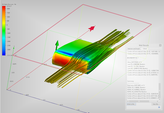
I spent less than 5 minutes knocking up a simple Aerofoil, of which I saved and placed into Simulation CFD as a parasolid.xt. After getting to know the software and applying the correct parameters I had a fully working model that was showing vector displacement, ribbon flows and aerodynamic forces working on the aerofoil. This aerofoil above was run using external incompressible flow. 


Autodesk website has a fairly extensive list of tutorials that are easy to run depending on your modelling skills:

http://www.autodesk.com/wikihelp-cfd-tutorial-2014-enu

8 Oct 2013

Woodwork for Inventor

Have you heard of the Woodwork for Inventor add-in yet?

This powerful upgrade to Inventor brings custom functionality for the design of furniture, cabinets, and joinery with specialist commands and environments such as edge banding, veneer directions and CNC preparation.

Graham Mansfield will be hosting webinars where you can tune in and see the software in action, so head on over to the site and register now:

Woodwork for Inventor Webinar

In the mean time, you can view a selection of videos listed on our main page

7 Oct 2013

Bamboo biking

New bicycles to the market can range from the out rightly ludicrously priced high spec Time Trial bikes seen in the pro racing environments right through to the 60 tonne steel things that sit on 2 random springs and end up collapsing with every pedal stroke. 

One bike that has entered the market by storm is some thing I became aware of while at Oxford Brookes University utilises some thing different; Bamboo. Bamboo is a grass that grows quickly, and after being cut down has little problem regrowing. 

Some small facts that accompany the material are such that it can absorb 5 times more CO2 and expel 35% more Oxygen than similar vegetation. Now you may think to yourself that this is just going to fall apart, but quite the contrary - they are fully built to British Standards and offer and extremely comfortable ride utilising its formidable absorption qualities. The bikes have even been tested and monitored using fatigue testing and extensive use of FEA. These bikes have been used in Alpine races right through to every day commuting.


Inventor Tip - Indented Parts List


Peter Barker - Micro Concepts Ltd


It used to be the case in previous versions of Autodesk Inventor that when you placed a parts list on to a 2D drawing of an Inventor assembly the parts list could be edited and there was a little plus next to the sub-assemblies so that they could be expanded (or not) as desired:


There is indeed still an option to place a parts list in this fashion and the name hints at its history: Structured (Legacy).


This then shows what I would refer to as an indented parts list:
 
So that’s great if you know you want to do that as you place the parts list onto the drawing but what if you decide to do so after you have placed it? You can’t edit the style of the parts list right?

Ok so just delete it and re-place it but of course this problem is exacerbated if you have placed the balloons because they will need to be deleted too.

If you have placed a Structured parts list (not legacy) and now you want to create an indented parts list do the following:

Right mouse click on the parts list and select Bill of Materials.

The Bill of Materials window will launch, in this window select the Structured tab. And from the View options drop down list select ‘View Properties’.


In the Level drop down select ‘All Levels’.


OK the structured properties dialogue box.

Select Done on the BOM Dialogue box.

Double click the parts list in the drawing and you should now have the ‘plus’ signs next to all the sub-assemblies so that they can be expanded.

4 Oct 2013

Autodesk Labs - Project Chronicle

If you have a need to capture interface workflows from within Autodesk products for the purposes of training or as webinars for your clients, Project Chronicle is now available on the Autodesk Labs website.

It combines video and audio capture with a timeline which displays the specific command clicks, dialogue box, file, and product used at each point in time, in sync with the video's playback.


There is a site dedicated to publicly available user created Chronicles here which already has around 600 uploads already, but users can also upload private Chronicles to keep their information and know-how to themselves and their organisation.

Project Chronicles will be available as a free download until 1st February 2014.


Inventor Tip - Rotate Leader Text

The Format Text dialogue for Leader Text can be quite misleading.  There is an apparent option to rotate the text, but it is  always greyed out.  This is because the form of the dialogue mirrors the standard Text dialogue box where it is an actual option.

In order to rotate leader text you need to edit the Dimension Style

Leader text alignment is not controlled by the Leader tree in the Styles Editor, but is found in the end tab in the Dimension tree:


Change the selection of the Leader Text Orientation drop-down box to "Aligned", as shown in the picture above.  Remember to save the style, and save it to the library if you want to use it globally across Inventor.

Now when you place a leader, make sure you place at least two line segments after the insertion point, as it is the end vertex of the second segment that can be used to rotate the leader text into the desired position:


This method should suffice for most situations, but if you require more options then look into creating a Sketched Symbol in your drawing, and save it to the template if you wish to re-use it across new drawings.

Peter Barker also reminded me to mention that whilst this works for leaders there are similar settings available to rotate text for Linear, Diameter and Radius Dimensions as shown in the following image.

3 Oct 2013

Inserting drawings into older Autodek software

On a day to day basis on the support Help desk at Microconcepts we get a fair few people asking how they can transfer or save their Inventor files in older versions of software. For example using Inventor 2013 and you need to open the drawing in AutoCAD 2012. 

From the Inventor idw, we can go to 'Save Copy As' via the 'Save As' tool in the Inventor home button. Now making sure you've selected the correct file format. If you move the cursor over to 'Options' on the bottom right hand corner of the 'Save Copy As' window and left click. 


Within Options you will be presented with pull down box options. Select the box under file 'File Version' in here you can select the software format you need that pre-dates the Software you are running. 


Mapping AutoCAD Block Attributes into Vault

In Vault, when you want to map properties from an Inventor file into Vault, it is a simple case of selecting that file at the mapping stage and choosing from the list of properties which are then populated in the Import Properties dialogue.

With AutoCAD block attributes, it's not so straightforward.  For these, you have to index them first on the ADMS console, which effectively requires access to your Vault server.

On the ADMS Console, go to Tools > Index Block Attributes

Create a New entry and give it the exact name of your AutoCAD block.  Here we are entering "Title1-1" which contains no link to any AutoCAD file - it is just a reference for now.

Adding an index for a block called "Title1-1"

Once you have the index in place, Vault will then be able to extract attributes from any AutoCAD file with a block which has that name, as properties.

On the Vault client, go to Tools > Administration > Vault Settings > Behaviours tab > Properties button

From here, either edit or create a new property and ensure it has an association.  It doesn't have to have the same name as the block but for clarity we have done so in this instance:


At the Import Properties stage, when you select the AutoCAD file containing the block, this window will now become populated with the attributes contained within.

2 Oct 2013

Inventor 2014 Service Pack 1

The first Service Pack for Inventor 2014 is now available for download:

Inventor2014_SP1_x86.msp (49272Kb)
Inventor2014_SP1_x64.msp (93768Kb)

Some of the issues addressed in this update (please consult the Readme for the complete list):

    Autodesk Inventor Professional 2014

      Cable & Harness
      • For some particular dataset, after placing a nail board view of a Cable & Harness assembly in a drawing file, Inventor unexpectedly exits when you close the drawing file without saving and then closing Inventor.

      Stress Analysis
      • Contacts in solids and faces at vertices are identified as face-face contacts. 
    Autodesk Inventor 2014


      Assembly Modeling
      • Cannot make a weldment iAssembly material valid as a weldable material. 

      Design Accelerator
      • Bolted connection does not update automatically when you repostion its location by changing the placement sketch point.

      Part Modeling
      • In the Insert iFeature dialog box, the help button is disabled if the iFeature is created with a legacy localization build.
      • iPart members do not show sketch and block definition.
      • iPart created from a feature with no dimension generates empty children.
      • When you measure distance in an iPart member, on the context menu Select Other is grayed out.
      • Mass calculation fails for a part that uses unpatched Rhino surface data.
      • ... more in the Readme

      Sketch
      • Cannot switch on and off the visibility of a sketch block when you edit the sketch.
      • Cannot create a coincident point when you attach a line to a projected point.

1 Oct 2013

New SpaceMouse Wireless

Connexion have released details of a new 3D spacemouse to add to their collection, and this time it's wireless:


SpaceMouse Wireless – The World’s First Wireless 3D MouseFor the first time, and due to very popular demand, 3Dconnexion’s 6-degrees-of-freedom sensor is combined with 3Dconnexion® 2.4 GHz wireless technology to deliver the reliability of a wired device, without the clutter of cords. 
 ·         Superior 3D Navigation – Intuitively and precisely navigate digital models or viewports in 3D space. With 3Dconnexion® six-degrees-of-freedom (6DoF) sensor technology.
·         Wireless Freedom – 3Dconnexion® 2.4GHz Wireless technology ensures a reliable, real-time connection to your 3D content.
·         Flexible Recharging - supplied micro-USB cable handles re-charging and data at the same time. Just connect and continue working.
·         Stylish Design - small footprint, elegant brushed steel base, two buttons.
·         Easy to Use – Each of the two SpaceMouse Wireless button opens its own radial menu providing convenient mouse-click access to four application commands.

See our retail webpage for the complete range of 3D controllers from Connexion:

http://www.microconceptsretail.co.uk/navigation-devices-18-c.asp

The spacemouse wireless will be available as of today, 1st October 2013 and will retail at £109 ex VAT.

SpacePilot Pro CAD Professional £299.00
SpaceMouse Pro CAD Professional £249.00
SpaceMouse Wireless CAD Professional £109.00
SpaceNavigator for Notebooks £79.00
SpaceNavigator CAD Professional £99.00