
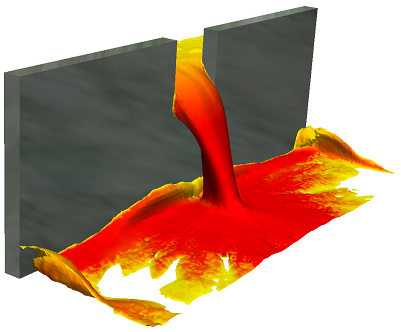
While the mathematical functions behind it are extremely complex, the setup of free surface is actually very simple. Here's a quick start guide to getting yourself up and running with a free surface analysis in Sim CFD. Keep the following image of fluid pouring through a gate in mind for our example.
1) Model only your fluid volumes. You will need at least 2 distinct solid bodies. Model a reservoir and a basin, and the gap that they will pass through (the gap can be part of the basin volume). There's no need to model anything else, since you will only be concerned with flow rather than heat transfer, unless you want to take wall roughness into account.
2) Launch your model into Sim CFD from the tab in Inventor.
3) Apply materials. All volumes should be the same e.g. water, even the initially empty volumes
4) Skip boundary conditions. We don't need any boundary conditions for this analysis since it is self-contained i.e. nothing enters or leaves the system.
5) Add an HOF initial condition to the reservoir fluid volume only - set the value to 1. HOF (height of fluid) is an on/off value (0 or 1) that instructs the application as to which particular fluid volume is filled at the start of the analysis. Any volumes not designated a height will be seen as empty.
6) Open the Solve dialogue.
- On the Physics tab, click Free Surface and check the Enable Free Surface box. Enter your gravity direction, which is usually negative Z (0,0,-1) but your model may vary.
- On the Control tab, the Solution Mode will default to Transient. You will want to set more save intervals than usual for smooth fluid flow visualisation at the end of your solve.
- Choose a large number of Time Steps (1000+) to Run then click Solve.
7) To visualise the results: right-click in space and choose Free Surface. You will then see the HOF value in action throughout the solution. For planes and ISO surfaces, choose VOF and plot as required. VOF at 0.5 represents the fluid-gas boundary.
S.C.
No comments:
Post a Comment