Showing posts with label simulation cfd. Show all posts

31 Mar 2014

Free Surface modelling in Simulation CFD 2014

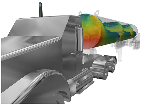
The 2014 release of Autodesk Simulation CFD Advanced/Motion brought with it the ability to simulate free surfaces in liquid volumes.  The applications of this are numerous and range from sloshing in tanks, the path of free flowing water, and hydrodynamic pumps and propulsion.


While the mathematical functions behind it are extremely complex, the setup of free surface is actually very simple.  Here's a quick start guide to getting yourself up and running with a free surface analysis in Sim CFD.  Keep the following image of fluid pouring through a gate in mind for our example.
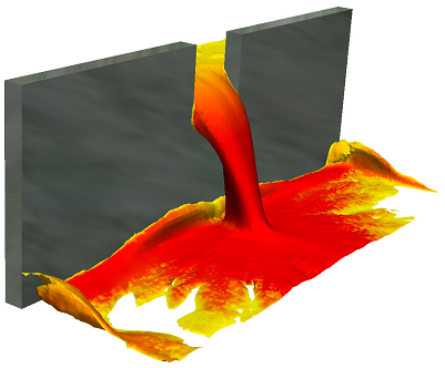

1) Model only your fluid volumes.  You will need at least 2 distinct solid bodies.  Model a reservoir and a basin, and the gap that they will pass through (the gap can be part of the basin volume).  There's no need to model anything else, since you will only be concerned with flow rather than heat transfer, unless you want to take wall roughness into account.

2) Launch your model into Sim CFD from the tab in Inventor.

3) Apply materials.  All volumes should be the same e.g. water, even the initially empty volumes

4) Skip boundary conditions.  We don't need any boundary conditions for this analysis since it is self-contained i.e. nothing enters or leaves the system.

5) Add an HOF initial condition to the reservoir fluid volume only - set the value to 1.  HOF (height of fluid) is an on/off value (0 or 1) that instructs the application as to which particular fluid volume is filled at the start of the analysis.  Any volumes not designated a height will be seen as empty.

6) Open the Solve dialogue.  
- On the Physics tab, click Free Surface and check the Enable Free Surface box.  Enter your gravity direction, which is usually negative Z (0,0,-1) but your model may vary.
- On the Control tab, the Solution Mode will default to Transient.  You will want to set more save intervals than usual for smooth fluid flow visualisation at the end of your solve.
- Choose a large number of Time Steps (1000+) to Run then click Solve.

7) To visualise the results:  right-click in space and choose Free Surface.  You will then see the HOF value in action throughout the solution.  For planes and ISO surfaces, choose VOF and plot as required.  VOF at 0.5 represents the fluid-gas boundary.

S.C.

4 Dec 2013

Simulation CFD 2014 Service Pack 2

This one has been available since September, but is worth highlighting for those new to the software.

"A service pack (SP2) has been released for Autodesk Simulation CFD 2014. This marks the second update available to Simulation CFD 2014 and can be applied without SP1 being install on your computer. In this service pack various defects were resolved. In this solution article you will find more information covering the highlights of the service pack, the patch file, and links to the release notes."

32-Bit Installer (.msp ~55 MB)
64-Bit Installer (.msp ~63 MB)

As always, follow the Release Notes before upgrading.

Highlights of Issues Addressed in this Service Pack:
  • The Thermal Comfort topic in the Help documentation was clarified to indicate that running radiation as a “0-iteration” analysis after the simulation is complete can improve accuracy in some cases.
  • The Simulation CFD launch command does not appear in the SolidWorks 2013 user interface.
  • The transient harmonic boundary condition does not produce the correct results distribution on the applied surface. 
  • The UGNX CAD Connection license is not being checked out correctly when launching from UGNX into Simulation CFD.
  • The average temperature reported on a Summary Part in the Decision Center is incorrect and different from the value reported in the Parts dialog box and in the Component Thermal Summary (CTS) file.
  • Absolute Pressure is displayed incorrectly when solid parts are included within the simulation.
  • The Help documentation contains an incorrect description of the path needed to manually configure the Simulation CFD launcher in UGNX.
  • A simulation that contains periodic boundary conditions exits unexpectedly and fails to complete.
  • Simulations that contain distributed resistance surface parts and are run with an analysis length unit other than meters do not predict the correct operating pressure for the fan
  • Locally installed Help documentation does not load on XP.
  • When opening a Simulation CFD 2013 Design Study file that was created on a non-English OS into Simulation CFD 2014, the localized string for “CAD Volume” appears as garbled text.
  • A particular Design Study causes Simulation CFD 2014 to crash when the simulation is opened after having finished running. 
  • In a design study containing multiple scenarios, right click on a non-active scenario, enable Adaptation and set the Solver Computer to Local. A crash occurs when activating this scenario after the simulation is complete.
  • Simulation CFD crashes if no solver computer is selected prior to clicking Solve to start the simulation. 
  • The indicated progress percentage is incorrect for a transient simulation that includes multiple inner iterations per time step. The indicated progress percentage can surpass 100%.